The Noggin Plus Setup menu will appear
After pressing 1 on the DVL’s main menu, allowing the user to edit the following parameters: system, cart, line, grid, GPS, and reset the defaults. These parameters will need to be changed to suit your survey.
Noggin Plus Setup Menu Screen:

GPR Noggin Plus Menu
System Parameters
Press 1 in the Noggin Plus Setup menu to view the system parameters. The proper system parameters are absolutely imperative in order to yield good GPR results and for presentation on the DVL. Parameters can be changed depending on the depth of the survey, the velocity of the material sampled (see other lessons about determining average velocities), the measurement units of depth and position, the type of antenna being used, the number of stacks, and the default setting for the gain.

GPR Noggin System Parameters
Press the appropriate button in the System Parameters menu to select an option.
1 – Depth
This setting determines the apparent depth the GPR will record, based on a user selected velocity. It is important to note that depth is an estimate and dependent on the average velocity (nanoseconds). GPR determines depth by measuring the time it takes for the radar signal to travel to and from an object at an assumed average velocity. D = V x T/2 Therefore, you need to make sure your velocity is set correctly if you want an accurate depth on the DVL screen. Remember, time is the measured quantity and estimated depths are calculated.
As a pointer, one of the best ways of reading depths from the DVL display
is by using the calibration function and setting the width of the hyperbola to the desired average velocity. Then place the peak of the hyperbola at a location on the screen where the user wants an estimated depth.
It is important to note that the Noggin Plus’s signal does not penetrate some subsurface materials very well. In this situation, the GPR system continues to collect data for a period equal to the chosen apparent depth. Locations where radar cannot penetrate the subsurface, the screen may appear blank or speckled. Poor results or a lack of GPR events does not mean that there are not any objects at depth or where the radar cannot penetrate!
2 – Velocity
This option sets the average velocity. The actual velocity often changes with depth, especially when the GPR signal passes through unlike materials. For the most accurate depth estimate, the velocity must match the material being surveyed. There are multiple methods to determine velocities. Sensors & Software recommends hyperbola matching. If the user does not know the average velocity of the subsurface material or a good velocity analysis cannot be performed, he or she may wish to use the table below to select an average velocity. No matter what process is used to find an average velocity, there is the possibility for an unknown margin of error.
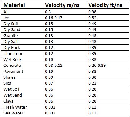
GPR Velocity Chart
If in doubt, a value of 0.0328 ft/ns or 0.10 m/ns is often selected and can be changed during post processing.
3 – Depth Units
The DVL can display the depth in three different units: meters, feet, and nanoseconds. Once again, note that the time it takes for the signal to travel to and from an object (above or below ground) is the only measured quantity. Depth is calculated. If nanoseconds is selected, lines are displayed as time lines. This is the amount of time it takes for the radar signal to travel to an object and back, which again is the only measured quantity in GPR (other than the amplitude). When you select meters or feet, all of the parameters should now be listed in that measurement system.
4 – Noggin System
Either the Noggin 250, Noggin 500, or Noggin 1000 needs to selected, depending on what antenna is being used with the cart. If the wrong antenna frequency is selected, the system will not function properly. It is imperative to select the antenna that you are using.
5 – Stacks
Occasionally, GPR will not obtain a good record. This, in part, can be due to cultural interference, electromagnetic interference, or subsurface materials that limit the GPR from penetrating to a desired target. When this occurs, a user can attempt to improve the signal strength and reduce noise through a process known as stacking. Stacking is very common and is the process of adding multiple traces together to create a single trace. For example, a stack of 8 means the DVL added the response of 8 traces together to form a single trace. Stacking helps to reduce noise. By definition, noise is random and does not stack very well. Since stacking occurs, more or less, at the speed of light, the process takes place while the cart is being pushed. The number of stacks can vary from 1 to 2048 in powers of of 2 (1, 2, 4, 8, 16, and so forth). Obviously, the more data that is stacked, the longer it takes to create a single trace to store in the DVL. Because a larger number of stacks take more time to collect, the SmartCart needs to be moved more slowly to avoid skipping traces. Therefore, it is important to be efficient. Perform the minimum amount of stacks possible to gather adequate data. In most cases, the default will yield desirable results. Newer versions of the software have a setting called DYNA Q. This option will appear if the stacks are set to zero. DYNA Q is a setting that works with the odometer. It takes more stacks when the odometer is rotated slowly and fewer stacks the odometer rotates quickly.
6 – Linear Gain
If the signal is weak, it can be amplified by adjusting the gain. The gain ranges from 1 (the weakest) to 9 (the strongest). While labeled a linear time gain, this is not a linear gain. The selection from 1 to 9 is linear but the gain is not. Adjusting the gain may allow the user to better observe a target on the DVL, in the field.
7 – Position Units
This option determines whether the odometer measures length in meters or feet.
Cart Parameters
Press 2 in the Noggin Plus Setup menu to adjust cart parameters. Cart parameters will help determine how data is collected. Cart parameters can be changed depending on the direction the cart is being moved, the trigger method, if one uses the auto start, and if an offset is applied for the arrow; in addition to setting the trip menu, the transfer rate and odometer selection are set here.

GPR Noggin Plus Cart Parameters
Press the appropriate button in the Cart Parameters menu to select an option.
1 – Cart Direction
The cart direction needs to be set depending on whether the user plans on pushing or pulling the cart to collect data. In general, it is easiest to push the SmartCart because the user can steer the cart while viewing the acquired GPR data on the DVL. This is especially important when trying to mark the ground with flags to denote a hyperbolic event.
2 – Trigger Method
The Noggin has three trigger modes: odometer, free run, and button. When the odometer trigger mode is selected, the Noggin begins a survey after being pushed or pulled a certain distance. This is probably the most common method of collecting data with the SmartCart. When free run trigger mode is selected, the Noggin Smart System begins to continuously collect data. This mode is often used with “search and mark” tactics in which a user collects data and marks targets on the ground with flags, paint, etc. After selecting the free run mode, the user must input the number of stacks and time delay between data collecting. The more stacks and larger time delays will result in the Noggin Plus collecting data at a slower pace. In the free run mode, it may be a good idea to set the station interval to 1 so the positions shown along the top of the DVL’s display corresponds to the number of traces. The third method is for the user to start data collection by pushing the B button on the DVL. Once pushed, the user must select the number of stacks to be recorded for each trace. Using a button as a trigger may be a good choice when trying to collect data at specific locations along a line.
3 – Auto Start
If the Auto Start option is turned on, the user can press Run, automatically booting up the Noggin for data retrieval. This setting is useful when collecting many lines of data in a grid. It prevents the user from having to constantly push the Start button and go through its options for each line.
4 – Arrow Offset
There is an arrow defining your position on the DVL screen. The arrow allows a user to backup to a specific location corresponding to the data image. This allows a user to stop and back up in order to mark the center of target on the DVL. By default, this arrow corresponds to the center of the Noggin but it can be changed so that the arrow is offset. Setting an arrow offset of +.10 meters will move the arrow to 10cm ahead of the Noggin’s center while a offset of -.10 meters would move the arrow to 10cm behind the Noggin’s center. It is important to note that the arrow offset will always be expressed in terms of meters regardless of the measurement system being used.
5 – Trip Menu
The Trip menu records the total distance the cart has traveled; it cannot be reset. The distance counter also records distance traveled but can be reset. The distance counter may be useful for documenting the distance covered during a survey. To reset the distance counter, select the Distance Counter and press the Zero button.
6 – Transfer Rate
The transfer rate is the speed at which the Noggin Plus sends data to the DVL. It can be set from 1 (the slowest) to 8 (the fastest). In general, the transfer rate should be set to 8. Only in situations where data cables longer than standard lengths should this parameter be adjusted.
7 – Odometer Number
Moving DVLs between carts and different types of terrain can lead to different calibration settings. Select the odometer being used. A different menu selection is used to calibrate odometers. Remember it is important to calibrate the odometer before use.
Line Parameters
Press 3 in the Noggin Plus Setup menu to adjust line parameters for a Line survey. Line surveys can be a quick and accurate method to collect data along random paths or along lines that are not conducted on an orthogonal grid system that have equally spaced parallel and perpendicular lines. As long as the starting point and ending point of a straight GPR line is known, the geometry can be edited so the line can be correctly positioned on an orthogonal grid system. Thus, GPR lines collected in this mode can still be used by 3-D post processing software. Line parameters can be changed depending on the starting position, line direction, and the relative spacing between acquired traces.

GPR Line Parameters
Press the appropriate button in the Line Parameters menu to select an option.
1- Start Position
The start position is the position where data acquisition begins. For more accurate results, start each line from a known and well documented location. Generally this is set to 0.0. However, if the user wants to start a data file at a different position, this number can be edited. For instance, perhaps the user is starting a survey 10 feet from a fence. In this instance, he or she may want to call your start position 10.0.
2 – Line Direction
The line direction can be set to forward or reverse, depending on which direction the line data will be collected. If the start position is 0.0 and the line direction is forward, the line will collect data at positions increasing in distance along the line (e.g., 0.1, 0.2, 0.3, etc.). If the starting position is set to 20.00 and the line direction is reverse, data will be collected in decrements counting down or decreasing along the line, such as 19.9, 19.7, 19.5, ect. In general, keeping the line direction to forward is the easiest and can be changed in post processing software with good field notes.
3 – Station Interval
As a Noggin Smart System is pushed (or pulled), it collects traces at fixed distances called station intervals. Station intervals that correspond to actual distance can only be recorded if an odometer it used. Smaller targets that require more detail need smaller station intervals in order to acquire traces that are spaced closer together. Larger objects may benefit from a larger station interval. Shorter station intervals lead to greater memory usage. Therefore, be mindful of the detail needed and have a good understanding of the sampling theory required to obtain desirable GPR results. Be aware that a quickly moving cart with a small station interval will likely drop or skip traces. In the free run mode it is often a good idea to set the station interval to 1 so the position along a line reflects the number of traces collected.
The station interval choices are: Short, Normal, Long, X-Long, Norm x10, Norm x20 , Norm x40, Norm x50, Norm x100.
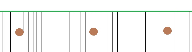
Example of Increasing Station Interval Spacings
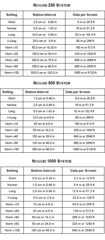
GPR Station Interval Settings per Sensors & Software
4 – Plot Interval:
The plot interval setting is the number of pixels dedicated per data trace or the width of the trace presented on the DVL screen. The default setting for the Noggin 250 is 2 pixels where as the default setting for both the Noggin 500 and Noggin 1000 is 1 pixel per trace. A user might adjust the plot interval to more pixels to more easily view data collected with a larger station spacing or to adjust the plot interval narrower to fit more data on to the screen. In general, the default options are adequate for most applications and only effects the presentation of the GPR results on the DVL.
Grid Parameters
Grid data is a collection of parallel and perpendicular GPR lines. In contrast, line data may consist of GPR data collected along random line paths, spacings, and locations. If collecting GPR data using a grid, it is important to designate the grid dimensions, line spacing, grid type (parallel lines or perpendicular lines), and survey format. Push 3 in the Noggin Plus Setup menu to set these parameters. In addition, if surveying for linear targets like pipes or facilities, the GPR will perform better if data lines are conducted perpendicular to these targets. Grid surveys are great for a more detailed analysis.

GPR Grid Parameters
Press the appropriate button in the Grid Parameters menu to select an option.
1 – Grid Type
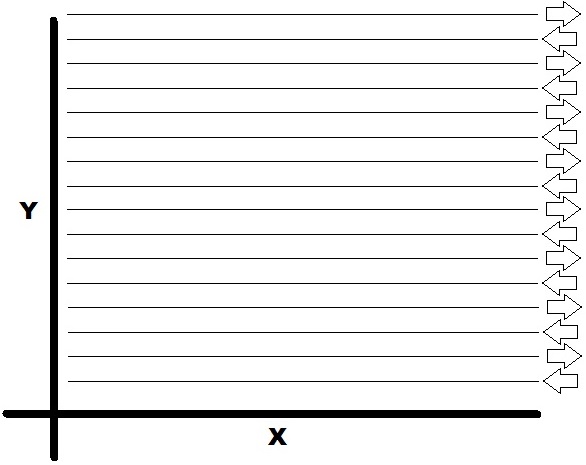
Determine which way the user will survey the grid. Grids can be setup with lines parallel to the X-axis or the Y-axis. For a more detailed GPR surveys, select the XY option to collect data along parallel and perpendicular lines. In other words, along lines that are parallel to both the X and Y axes. When picking the XY option it is especially important to survey the lines in the correct direction in order to “match” the X and Y data.
2 – Line Spacing
Determine the amount of space between data lines in the grid. Grids with lines collected parallel to only the X-axis need X values; whereas, grids with lines collected parallel to only the Y-axis need Y values. Grids with lines parallel to both X and Y axes need both X and Y values but do not need to be the same. Line spacing is important! Smaller targets require a tighter line spacing. Therefore, be mindful of the detail needed and have a good understanding of the sampling theory required to obtain desirable results. In general, it is not unreasonable for the Noggin 250 to have lines spaced 18 inches apart, the Noggin 500 to have lines spaced 9 inches or less, and the Noggin 1000 to have lines spaced 4 inches or less. An improper line spacing can lead to gaps in the data, which may lead to aliasing, misleading results, and/or poor post processing results. A common mistake users make to reduce the amount of time to conduct a GPR survey is to space lines too far apart. Lines spaced close together not only better defines a target at depth but often provides redundancy that increases ones confidence in the results. Many parameters of your survey can be changed in post processing but nothing can change the amount of raw data collected, except resurveying. Please exercise common sense.
3 – Grid Dimensions
Before conducting a grid survey, the dimensions of the X-axis and Y-axis must be entered. Enter these numbers using the same measurement units as the selected position units. The dimensions of the grid in combination with the line spacing will determine the number of lines collected during the survey. Obviously, the larger the grid and the smaller the line spacing, the more lines and time are needed to complete a survey. The user can toggle between the X and Y axes by pushing the X/Y button. Once highlighted, the line number can be altered. It is recommended to complete one axis before starting the other. This will assist with starting and ending at the same locations along base lines. Spatial positioning is especially important with a grid survey; be as accurate as possible.
4 – Survey Format
The survey format determines how data lines will be collected. In general, data lines are gathered by going in the Forward direction. However, in larger surveys it will save time to collect data in the Forward direction and then return along a line in the Reverse direction. This is called the Forward and Reverse survey format. If using this survey format, it is important that the odometer is calibrated, grid dimensions are correct and accurate, and the starting and ending baselines are consistent. For smaller surveys, it is recommended to use the same direction, such as forward, and make certain that you are starting at the same point along a base line to ensure accurate results.
Forward and Reverse Survey
GPS Parameters
The DVL has the ability to be connected to a GPS system through a serial port. Press 4 on the Noggin Plus Setup menu.

GPR GPS Parameters
Press the appropriate button in the GPS Parameters menu to select an option.
1 – Mode
Once connected, the DVL can log information from an attached GPS system into the DVL. There are 3 GPS settings: off, reading every X traces, and fiduciary tagging. Off is the setting if GPS is not being connected or used. GPS is usually only needed on very large scale surveys. Reading every x traces is a setting that collects GPS data every predetermined number of traces. The GPS information will be saved with the same name as the data file except with a different extension. This makes it easy to keep track of which GPS files belong to which survey line. Fiduciary tagging is a setting that collects GPS data whenever a fiduciary marker is marked. This is a common way to note spatial positioning when continuous collecting data on an irregular line. Be aware that the spacing between traces is often much much less than the accuracy of the GPS. Thus, GPS may be a great way to place the lines on a map but it is unlikely a good choice for accurately placing traces along a line. The odometer is generally considered one of the best methods of measuring distances along a line.
2 – Baud Rate
The Baud rate must be matched to the GPS. Options are 2400, 4800, 9600, or 19200. 9600 is the default.
3 – Stop Bits
The Stop Bits has default of 1 but can be set to 2.
4 – Data Bits
The Data Bits has a default of 8 but can be adjusted to 7.
5 – Parity
Set to None, Even, or Odd
6 – End String
GPS can often send three different types of end strings: GPGGA, GPVTG, GPGSA. Select the End string that is needed for the survey. Press A to run System Test 1 to see a string from your GPS and confirm the end string.
A – System Test #1:
This test runs to see if the DVL is properly hooked up and working with the GPS. The GPS will take readings and send its informational strings to the DVL to display.
B – System Test #2:
This test can be used to graphically display GPS data such as time, latitude, longitude, and altitude on the DVL. It also has a zoom feature.
Besides the mode you select, GPS settings may be determined by the GPS manufacturer.
Set Defaults:
This option resets all the parameters to the factory, default settings. This may be a good way to clear all the parameters from the last survey or user. This allows the user to start fresh and to begin setting the parameters of his or her newest survey.

Set Defaults Menu
To exit the Noggin Plus setup menu press #8