pulseEKKO PRO TR1000
runs on the same software as any other pulseEKKO PRO system. However, it possesses some attributes that need to be specifically discussed. Obviously, its assembly is going to be different because of its distinctive configuration. This configuration is suited for specific applications such as concrete scanning and infrastructure scanning that need different parameters for detailed surveys. For this reason, the pulseEKKO PRO TR1000 Supplementary Information Page contains lessons on assembly, odometer calibration, and data collection specific to the TR1000.
pulseEKKO Pro TR1000 Assembly
1. Unpack system and accessories from the shipping container.
Organize items as needed. (Some components of the cart may already be assembled from the rental company. This guide will focus on the complete assembly of the TR1000 in the event that the user must put it together from the beginning.) Note: Ensure the control module is connected to the DVL before assembly.
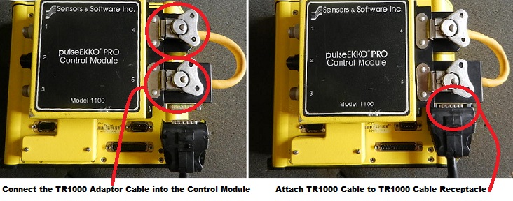
2. Connect the TR1000 Adaptor Cable to the DVL.
This cable connects the two transducer cable receptacles together on the control module. The cable receptacle on the adaptor cable should be towards the bottom of the DVL.
3. Connect the pulseEKKO PRO TR1000 Transducer Cable to the Adaptor Cable and TR1000.
pulseEKKO PRO TR1000 DVL Cable End Not Attached and Attached
The male end of the transducer cable plugs into the adaptor cable while the female end connects to the TR1000. The transducer cable can vary in length.
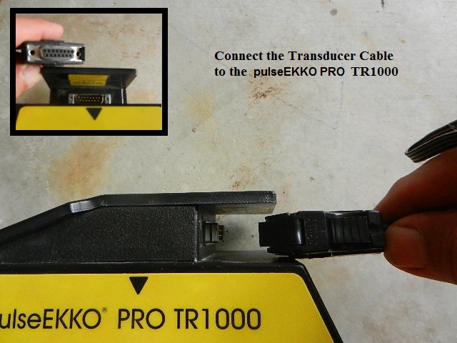
Connect the Transducer Cable to the pulseEKKO PRO TR1000
Note: Squeeze the connecter release tabs to disconnect the transducer cable from the TR1000.
4. Connect the handle (optional).
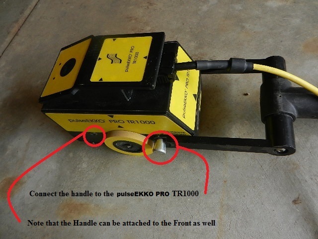
Connect the handle to the pulseEKKO PRO TR1000 v1
Pull the rear spring-loaded handle knobs outwards to slide the handle into position. The spring-loaded knobs should lock the handle into place. There are also a pair of holes on the front of the TR1000 to mount the handle, if the sensor needs to be pulled rather than pushed. After the handle is in place, use one or two strips of two-sided Velcro to attach the cable to the handle. The handle should be in placed flat against the floor so enough slack is available in the cable to avoid stress on the cable connector.
5. Find the pulseEKKO PRO battery pack and locate the power supply cable.
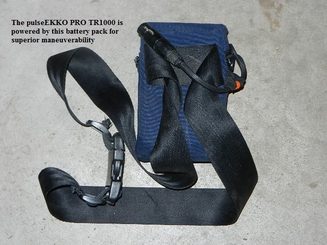
pulseEKKO PRO Battery Belt Pack
Connect the Power Module Cable and Power Supply to the DVL.

Connect the Power Supply to the DVL
Finished pulseEKKO PRO TR1000 Assembly
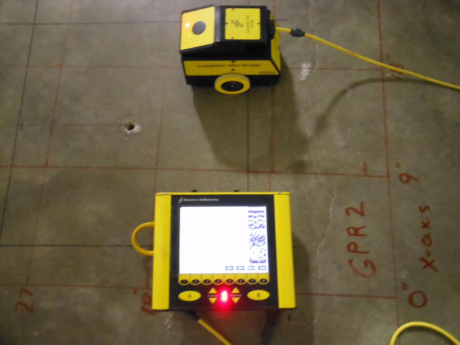
TR1000 and DVL III GPR
pulseEKKO PRO TR1000 Odometer Calibration
Odometer Calibration is vital to an accurate TR1000 survey.
Odometer calibration should be done before any data collection occurs. Dismissing the importance of accurate spatial positioning by neglecting to calibrate the odometer is one of the biggest mistake that new GPR users commit besides misunderstanding how average velocity is used to calculate depth estimates. Unlike some of the lower frequency antennas, the 1000 MHz system is capable of mapping small lateral variations. Thus, it is important to have the best calibration as possible. It may not be obvious at first or for small 2 by 2 foot survey areas, however, a poorly calibrated odometer pushed along a 30 foot line may yield distances that may be much more or much less than the actual length surveyed (e.g. a tiled floor with wide and deep grout lines will yield a slightly different survey dimension than a survey area consisting of smooth concrete). While post processing methods can assist with revising spatial distortions, it is difficult to explain to an end user why the grid dimensions do not correlate well with the area surveyed, if not corrected.
From the Acquisition Control Menu, enter the pulseEKKO PRO TR1000 Odometer Calibration Setup menu.
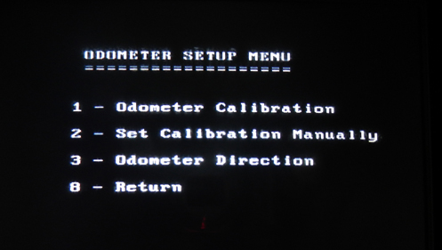
pulseEKKO PRO TR1000 Odometer Setup Menu