pulseEKKO PRO SmartCart Assembly
1. Unpack SmartCart and accessories from shipping container.
Organize items as needed for the pulseEKKO PRO SmartCart Assembly. Some components of the cart may already be assembled. This guide will focus on the complete assembly of the SmartCart in the event that the user must complete an entire assembly.
2. Connect the front axle assembly to the cart body (separation bars).
Insert and tighten the finger screws, shown below
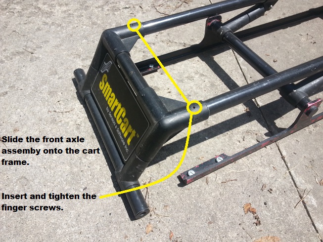
Attach the Front Axle
Before installing the rear axle assembly, rotate and connect the handle support into its upright position. To install the support arm to the handle, rotate the handle and the support arm until the support arm is on the far side of the grip. Remove the clevis ring from the handle support arm and bring the handle to the upright position. Connect the handle support arm to the handle by inserting the support arm into the handle’s T-shaped tube. The T-shaped tube may need to be adjusted to get the proper angle to insert the support arm. Finally, insert the clevis pin to fasten the handle support arm and handle together. Now, attach the back axle assembly (with handle) on to the cart body or opposite end of the separation bars. Insert and tighten the finger screws as shown below.
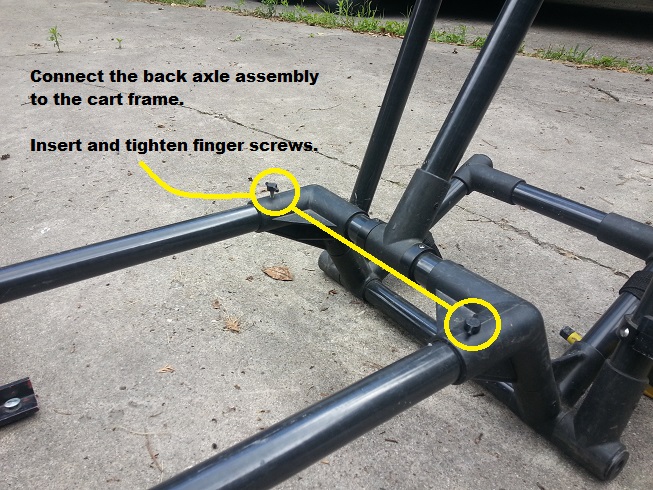
Attach the Back Axle Assembly
3. Connect the antenna hangers, attachment brackets, and antennas.
Note that different antenna sizes will have different separation bars and hangers for the antennas. The hangers must be installed with the quarter-turn quick connectors facing inwards. The attachment brackets are held in place with clevis pins.
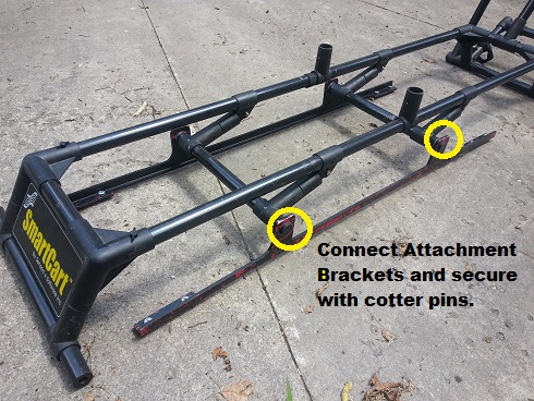
Connect hangers and brackets during the pulseEKKO PRO SmartCart Assembly
4. Setup the antennas, transmitter, and receiver electronics.
Prepare both antennas by screwing two male connector pins into each antenna, finger tight should work. Then remove the plastic bases from the transmitter and receiver electronics and attach to the antennas via the four quarter-turn fasteners.
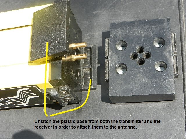
Attach the Tx and Rx Base to the Antenna
Sometimes it is necessary to turn the fasteners slightly counterclockwise before the bases will insert into the antenna mounts and the fasteners can be tightened.

Attach the pins and fasteners
Insert two batteries into the receiver electronics case and two batteries into transmitter electronics case. Before trying to close a compartment door, make sure the battery is orientated correctly and that the bottom of each battery is inserted as far as possible in to the battery holder’s base. This is a tight fit. It will be impossible to swing the battery in to its final position unless the battery is properly seated.

pulseEKKO PRO TX and RX battery inserted into holder
Next thread and finger tighten two female connector pins to the bottom of the transmitter and receiver electronics. At this point, make sure to be careful not to bend or break off the exposed pins. With both the transmitter and receiver facing the same side of the cart, insert the electronics into place on each antenna. Place the receiver on the front antenna and the transmitter on the back antenna. The same plastic clips that held the bases to the electronics during storage hold the electronics on to the bases when fastened to the antennas. Next, connect the antennas with the electronics to the attachment bars. The antennas fasten with four quarter-turn connectors, the same way the plastic bases were attached to the antennas.
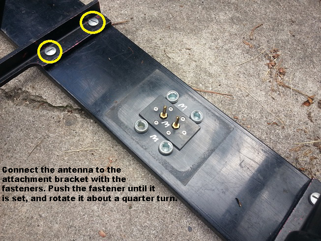
Attaching the Antenna
5. Attach the four wheels.
Insert two wheels in to the front axle assembly and two in to the rear axle assembly.
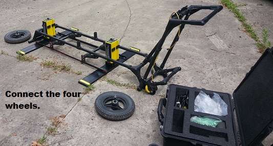
Attach the Wheels to the Cart
Each axle has a push button on the center of the outside hub of the wheel that allows the axle to slip in and lock into place. Note that the odometer has to make good contact with the rear wheel.
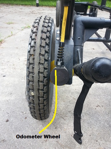
Odometer Wheel
Check that the odometer wheel is making proper contact with the cart’s wheel. Push the cart; if the odometer wheel isn’t making proper contact, distances will be wrong and GPR data may not appear on the DVL display. At times, though seldom, it may be necessary to adjust the position of the odometer. To do so, loosen the odometer unit with a 1/4th Allen wrench. Reposition the odometer, making sure the odometer is making good contact (not excessive) with its wheel, and tighten the screws.
6. Secure the DVL battery into its angled basket located on the back of the frame under the handle.
Battery and its Compartment
Position the battery so that its handle is facing the user and the battery port is on the right hand side. Buckle the straps to restrain the battery. Insert the round 4 pin cable in to the battery’s port. Sometimes it is necessary to rotate the plug before it will snap into place.
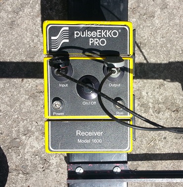
7. Snap the Digital Video Logger (DVL) with Control Module into its support shelf.
Locate the support shelf near the front of the cart’s handle. Align the DVL with the support shelf and slide it down towards the clips until it snaps into place. Gently move the DVL to make certain that it is held in place. Note that the compact flash drive is shown sticking out of the top of the DVL. The compact flash is used for transferring data to a PC.
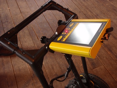
DVL snapped into support shelf
The support shelf’s angle can be pivoted to improve visibility of the DVL. If the support shelf will not pivot, slightly loosen its hand screws located on the bottom side of the shelf.
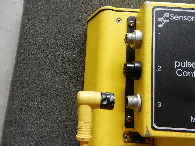
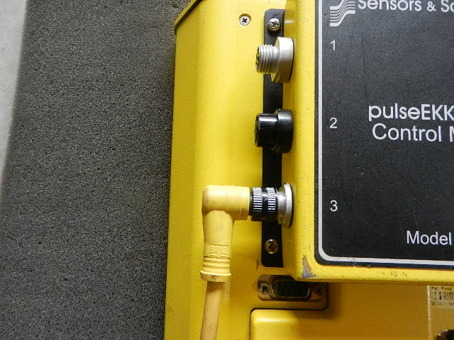
8. Connect the cables.
Connect one fiber optics cable to the transmitter and one to the receiver with the color-coded plugs. Match the colors of the plug ends with the colors on the ports of the transmitter and receiver. The opposite end of each cable plugs into an optical coupler on the DVL. Two optical couplers are attached to the control module located on the back of the DVL. The end of the fiber optic cable that plugs into the optical coupler is keyed and will only fit in one orientation. The plugs gently snap into the ports, do not force. The Transmitter cable should connect to the receptacle labeled 4 while the receiver cable should connect to the receptacle labeled 5.
Fiber optic cables connected to color-coded ports
The last two connections to be made are the battery and odometer cables. These connect to one side of the DVL Control Module. Note the number of pins and key-way for each plug. Match to the appropriate port. Insert each cable end in to its port and gently rotate until the key-ways match. Gently push the plug in while tightening the outer sleeve. Continue to tighten until the plug is fully inserted into the control module. Do not over tighten.
pulseEKKO PRO Power Cable End Not Attached
pulseEKKO PRO Power Cable End Attached
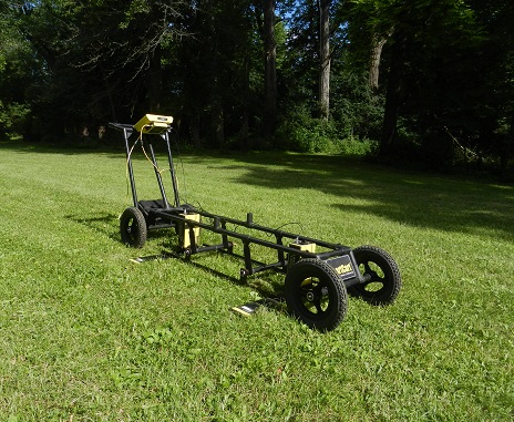
Finished pulseEKKO PRO SmartCart Assembly with SmartCart
pulseEKKO PRO SmartCart