pulseEKKO PRO System Setup Menu
is accessed by pressing 2 in the Main Menu. Once in the system setup menu, press the appropriate numbered button to access each sub-menu.
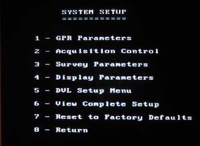
pulseEKKO PRO System Setup Screen
pulseEKKO PRO Acquisition Control Menu
is accessed by pressing the number 2 button. This menu deals with both how to trigger data collection and spatial positioning. Both of which are of utmost importance.
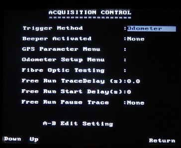
pulseEKKO PRO Acquisition Control Screen
Use the Up and Down buttons to toggle between each parameter. Edit the values with the A and B buttons. Recommended values are indicated by an asterisk.
Trigger Method
Determine what is going to trigger the transmitter to send a GPR radar signal. There are five trigger methods: DVL B button, electrical trigger, fiber optic trigger, odometer, and free run mode. The best trigger method is going to depend on the survey conditions and objectives. Trigger methods such as a button or electrical trigger are best used for surveys in areas where navigation is difficult. It may be useful for small areas or specific locations along a line. Given the configuration of the SmartCart and TR1000, the DVL B button is more likely to be used than an electrical trigger for these types of readings. The odometer is best suited for a SmartCart as well as TR1000 surveys because of their configurations and applications. It’s no surprise that this is the most common method of collecting data with the SmartCart and TR1000 pulseEKKO PRO systems. In free run mode, the pulseEKKO PRO continuously acquires data. Free run data collection works well for “search and mark” tactics where the operator marks targets on the ground with flags, paint, etc. After selecting the free run mode, the user must input the number of stacks and time delay between records. The more stacks and larger time delays will result in the GPR collecting data at a slower pace. In the free run mode, it may be a good idea to set the station interval to 1 so the positions shown along the top of the DVL’s display corresponds to the number of traces.
Beeper Activated
Enable or disable whether the equipment beeps when the trigger button is pushed. This is purely user preference. When pushing a button or electrical trigger to collect data, it can be useful to ensure data collection points are not missed.
Free Run Trace Delay
Specify a time delay between collecting data traces in free run mode. This allows time to move the antennas to the next station location, if a SmartCart is not used.
GPS Parameter Menu
Press A to access the GPS Parameter Menu. GPS is sometimes used for large SmartCart surveys. GPS is rarely, if ever, used by the TR1000 system.
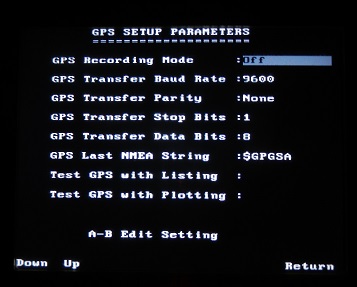
pulseEKKO PRO GPS Setup Parameters Screen
Use the Up and Down buttons to toggle between each parameter. Edit the values with the A and B buttons. Recommended values are indicated by an asterisk. GPS parameters are going to vary depending on the manufacturer and type of GPS unit. Always use the parameters recommended by the GPS company.
GPS Recording Mode: There are 3 GPS settings: off, reading every X traces, and fiduciary tagging. Off is the setting if GPS is not being connected or used. GPS is usually only needed on very large scale surveys. Reading every x traces is a setting that collects GPS data every predetermined number of traces. The GPS information will be saved with the same name as the data file except with a different extension. This makes it easy to keep track of which GPS files belong to which survey line. Fiduciary tagging is a setting that collects GPS data whenever a fiduciary marker is marked. This is a common way to note spatial positioning when continuous collecting data on an irregular line. Be aware that the spacing between traces is often much less than the accuracy of the GPS. Thus, GPS may be a great way to place lines on a map but it is unlikely a good choice for accurately placing traces along a line. The odometer is generally considered one of the best methods of measuring distances along a line.
GPS Transfer Baud Rate: The baud rate is the speed from which the GPS sends data to the DVL. It can be set to 2400, 4800, 9600, or 19200. The default is 9600 but often must be set to 4800, depending on the requirement of the GPS unit.
GPS Transfer Parity: Parity can be set to None, Odd, or Even. None is the default.
GPS Transfer Stop Bits: The available stop bits are 1 or 2. 1 is the default.
GPS Data Bits: The available data bits are 7 or 8 with 8 being the default.
GPS Last NMEA String: Attach the correct GPS prefix to the last GPS string: either GPGGA, GPVTG, or GPGSA . If the GPS string is not known, run the Test GPS with Listing Function and note the first 5 characters of the last line. Theses are the characters need for the Last NMEA String.
Test GPS with Listing: After all the GPS settings are programmed, run this function to check the output. If there is no output, check the settings and your connections.
Test GPS with Plotting: After the GPS us running properly, the displays shows the time, latitude, longitude, and altitude as well as plotting the data. Check for accuracy.
Odometer Setup Menu
A correctly calibrated odometer is the basis for recording and maintaining proper spatial positioning during a survey. Many new users neglect to properly calibrate the odometer and the survey positioning is inaccurate as a result. Take initiative and properly calibrate the odometer as the first step to a successful survey. Visit this menu to calibrate the odometer. The odometer should be calibrated before every survey.
Fiber Optic Testing:
If an error occurs relating to the transmitter and/or receiver, check for power and make sure all connections are secure. If these procedures do not provide a solution, perform a Fiber Optic Test. Test the Fiber Optic Cables for damage.
Exit pulseEKKO PRO Acquisition
by pressing key 8.